MTBF
What is MTBF? – Mean Time Between Failures
The Mean Time Between Failures (MTBF) is a measurement of the relative reliability of a power supply based upon a statistical calculation, not a measurement. All the parts in a power supply have mean time between failure ratings. These are mathematically combined to get an MTBF figure, often dependent on the stress put on them. This is done according to MIL-HDBK-217.
The MTBF is not the time it takes for a power supply to fail, it is the total functional life of the supply divided by the number of failures. This means that a low MTBF shows that the power supply will fail several times as compared to one with a higher value. The values affect the performance and reliability of the power supply or equipment.
The bath tub curve
The MTBF applies to a combination of components and processes and more specifically during the products normal operating phase with a constant failure rate. It is therefore not applicable to the period where the equipment suffers from ‘early failures’ or ‘wear out’ failures as shown in the bathtub.
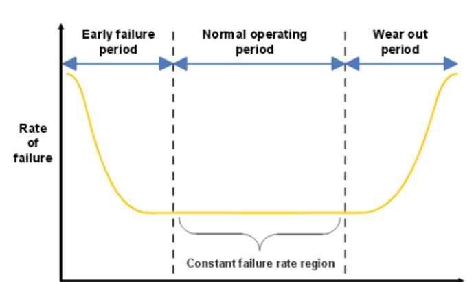
Figure 1: Bathtub curve showing of failure rates of a product – Image Credit
Factors that affect the MTBF value and reliability
The reliability is dependent on a combination of factors, which includes the components, design and analysis, manufacturing process, testing, burn-in and applications.
The MTBF is directly related to the design, tolerances and quality of the individual components. It is influenced by the types and ratings of the capacitors and other components. The more reliable circuits have components with a bigger margin or higher ratings. This means that they operate in conditions much lower than their maximum ratings. This may be more expensive, but provides a longer service life.
However, even with a high MTBF figure, the stress on the equipment may further influence its operations, and the MTBF value becomes lower when under stress that is more than design parameters.
The MTBF ratings usually assume ideal manufacturing processes and proper application of the device. However, in an ideal situation, some components suffer from a few manufacturing defects while equipment may work under higher temperatures and more load than anticipated. These factors will definitely lower the MTBF value and the reliability of the equipment.
Capacitor failures are more frequent compared to other components. The capacitor failures may lower the MTBF value than what is provided, especially when under stressful operating conditions such as
- Using low voltage rating capacitors
- High operating temperature
- Physical size, large diameter capacitors have higher values and lasts longer, however the space may not allow the bigger capacitors and this may limit the type of device to use.
Other factors that affect the average load time are:
- Effect of continuous operation
- Ambient temperature
- Vibration
- Quality of power: Power disturbances such as spikes and overvoltage may shorten the life of most components.
Determining the MTBF of a an equipment
Manufactures usually indicate the MTBF value on their equipment, however, a more accurate and reliable value is determined when the power supply is put under test in the actual field.
One of the operational factors that lower the reliability of components such as capacitors and semiconductor devices is the temperature. For example, a temperature increase of 10 degrees Celsius decreases the life of a capacitor by 50 percent.
For this reason it is necessary to test power supplies under different temperatures when determining the MTBF. By testing at the specific temperature, manufacturers can closely estimate the reliability values at the intended real-world application.
Determining the MTBF
There are several methods of determining the MTBF value; some are based on statistical data of the components, while others are based on actual field tests. The commonly used methods include:
- MIL-HDBK-217F
- Siemens
- Bellcore
- CNET
- HRD4
- Fault Tree analysis
- RBD (Reliability Block Diagram)
- HALT (Highly Accelerated Life Testing
- The Markov Model also known as the State Space Diagram
- FMEA/FMECA (Failure Mode and Effects Analysis / Failure Mode, Effects and Criticality Analysis)
Siemens-norm SN 29500
The MTBF testing is carried out at higher ambient temperatures of about 40 degree Celsius (104 degrees F). In addition the methods take into account the:
- Number of the components in the circuit
- The full power load that the device will be subjected to
- The actual operating temperature
This method provides a more reliable value based on actual operating environment.
MIL-HDBK-217F
The MIL-217 was originally developed for mission critical systems such as the aerospace and military. However, reliability prediction model is nowadays used for both the defense industry and the commercial companies.
It relies on the “Military handbook, Reliability prediction of Electronic Equipment” MIL-HDBK-217 which contains the failure rate models for a wide range of electronic components including transistors, diodes, integrated circuits, capacitors, resistors, switches, connectors, relays and more. The method has more detailed calculations for the failure rate data. The calculated MIL-217 results will indicate higher failure rates compared to rates from other methods such as the Bellcore standard.
Conclusion
The MTBF is an indication reliability of a repairable machine. When selecting a power supply, it is important to pay attention to the MTBF because this directly related to the useful life of the power supply. A high value means that the equipment will function for a long time before any of the components fail.